E-Mail: sales@microapproachmed.com
Phone: +86-17722685792
- All
- Product Name
- Product Keyword
- Product Model
- Product Summary
- Product Description
- Multi Field Search

Views: 0 Author: Site Editor Publish Time: 2026-10-23 Origin: Site


In advanced medical device manufacturing, the structural integrity and atraumatic performance of a catheter dictate its clinical viability and regulatory approval. Engineering teams often face yield losses, delamination, or inconsistent flexibility profiles because the distinct thermal and mechanical boundaries between reflow, tip forming, and curve shaping are not perfectly aligned with their equipment capabilities. Understanding the exact material phase changes induced by each process is critical for technical evaluation. This guide breaks down the physics of each operation and provides a framework for evaluating a catheter laminating machine and related forming equipment to ensure scalable, compliant production. We examine the exact thermal dynamics required to fuse composite shafts, reshape distal ends, and induce permanent polymer memory. By aligning material science with machine capabilities, production engineers can eliminate common defects like exposed braiding, flash, and spring-back.
Reflow (Lamination) dictates structural integrity: It relies on radial compression and precise thermal application to fuse discrete layers (liner, braid/coil, jacket) into a unified composite matrix without degrading the polymer.
Tip forming requires localized precision: Reshaping a thermoplastic end into an atraumatic profile demands strict control over heat, mold pressure, tension, and rapid cooling to prevent flash and material degradation.
Curve shaping alters polymer memory: Inducing permanent bends requires specific annealing and stress-relief cycles that differ entirely from the melting phases of reflow.
Equipment selection hinges on validation readiness: The right catheter manufacturing equipment must offer repeatable, data-logged parameters (temperature, speed, tension) to satisfy IQ/OQ/PQ validation requirements and integrate seamlessly with adjacent assembly processes.
Reflow integrates three primary components into a single composite shaft. These include the lubricious inner PTFE liner, the metallic reinforcement layer, and the outer thermoplastic jacket. The PTFE liner requires chemical etching—typically a sodium-ammonia treatment—to remove fluorine atoms and create a carbonaceous surface that allows the outer jacket to bond. The reinforcement usually consists of a stainless steel 304V or nitinol braid or coil, specified by its picks per inch (PPI) or wire diameter. Manufacturers rely heavily on assembly aids during this phase. FEP heat shrink fusing sleeves are placed over the assembled layers. As heat is applied, the FEP sleeve shrinks to apply uniform radial compression. Simultaneously, the outer jacket melts and flows through the interstices of the metallic reinforcement. This flow bonds the outer jacket directly to the etched surface of the inner liner.
The reflow process drives the outer jacket from a solid state into a highly controlled melt phase. Viscosity control determines the success of this transition. If the polymer becomes too fluid, it pools and causes uneven wall thickness. If it remains too viscous, it fails to penetrate the reinforcement layer, leading to delamination. Engineers must prevent thermal degradation and oxidation during the heating cycle. Overheating breaks down polymer chains, compromising the mechanical strength of the final device. Following the thermal cycle, operators must safely skive or peel the FEP fusing sleeve. This post-process step requires specialized slitters to score the FEP without cutting into the newly formed composite jacket.
Selecting the right equipment requires a deep understanding of thermal dynamics and mechanical alignment. Equipment capabilities directly influence the yield and performance of the final shaft. Vertical lamination systems use gravity to keep the internal mandrel straight, reducing the bowing often seen in horizontal setups.
The thermal nozzle and the pulling mechanism must maintain absolute concentricity throughout the heating cycle. Proper tensioning and centering create uniform tubing. Poor concentricity leads to polymer pooling on one side of the shaft, creating thin spots on the opposing side. Thin spots result in exposed braiding, which automatically fails quality inspections and poses severe clinical risks.
Thermal profiling depends heavily on the heat zone configuration. Single-zone heating offers simplicity but limits control over complex, multi-durometer shafts. Multi-zone heating allows engineers to create precise temperature gradients. A typical setup includes a pre-heat zone to initiate FEP recovery, a primary melt zone to flow the jacket, and a smoothing zone to finalize the surface finish. This configuration ensures longitudinal consistency when transitioning between different polymer blends along the catheter length.
Precise control over the traverse speed prevents localized burning. The speed at which the catheter moves through the heat source dictates the total thermal energy absorbed by the polymers. Uncontrolled speeds lead to incomplete lamination or severe material degradation. Tension control keeps the internal mandrel straight, preventing warping during the melt phase.
Different heating modalities suit different production environments. Hot air convection provides uniform, gentle heating suitable for standard thermoplastics. Radiant infrared (IR) systems offer faster heat transfer and penetrate deeper into the polymer matrix. Laser reflow systems deliver pinpoint accuracy for micro-catheters but require higher initial capital and strict safety protocols. Production throughput and material compatibility dictate the ideal choice.
Defect Type | Visual Indicator | Root Cause | Machine Adjustment Required |
|---|---|---|---|
Delamination | Jacket peeling away from the liner or braid. | Insufficient heat or jacket viscosity too high. | Decrease traverse speed or increase zone temperature. |
Exposed Braid | Metallic wires visible on the outer surface. | Poor concentricity or excessive FEP compression. | Realign the thermal nozzle and check mandrel tension. |
Polymer Degradation | Brown or yellow discoloration of the jacket. | Excessive thermal energy breaking polymer chains. | Increase traverse speed or lower the primary melt temperature. |
Fish-eyes | Small, un-melted bumps on the surface. | Uneven heating or moisture in the polymer. | Ensure uniform airflow and verify material desiccation. |
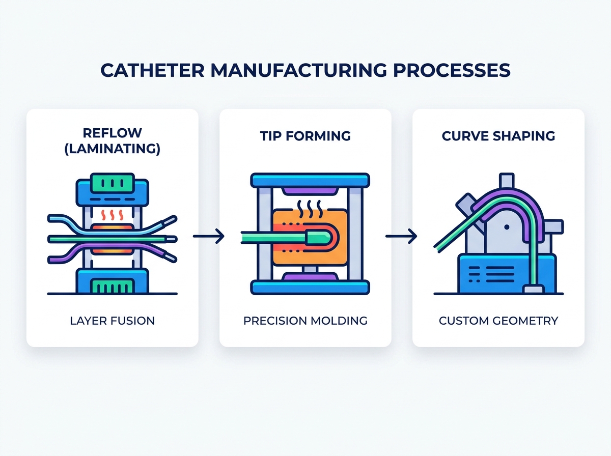
Tip forming transforms a blunt, extruded tube into a safe, atraumatic profile designed for vascular navigation. The process involves three main steps. First, operators slide the extruded tubing over a stainless steel or PTFE-coated mandrel. Second, the assembly enters a heated mold. This heating and forming stage softens the polymer, allowing it to take the shape of the die cavity. Finally, the cooling phase locks in the new geometry. Rapid cooling prevents the polymer from relaxing back into its original extruded shape.
Unlike reflow, tip forming does not fully melt and fuse disparate layers. Instead, it reshapes the polymer through controlled flow, tension, and pressure. The material softens just enough to become pliable. Precise insertion tension prevents the catheter shaft from buckling as it enters the die. Mold pressure dictates the final external profile. The balance between forward pressure and thermal energy ensures the material displaces evenly without creating internal voids or external flash.
A high-quality catheter tip forming machine balances thermal output with mechanical precision. The tooling and heating technology directly impact cycle times and geometric accuracy. Establishing a repeatable process requires strict adherence to setup protocols.
Verify die cavity dimensions and surface finish using optical comparators before installation.
Set the insertion servo speed to match the specific melt flow index of the polymer being formed.
Calibrate the heating generator output to prevent localized burning or incomplete material flow.
Establish the cooling water flow rate to ensure rapid crystallization of the polymer chains.
Perform a destructive pull test on the finished tip to verify tensile strength and layer adhesion.
Heating technology defines the efficiency of the tipping process. Radio Frequency (RF) heating generates rapid, localized heat directly within the metallic mold. This minimizes the heat-affected zone on the catheter shaft and suits complex geometries like dilators or soft tips. Traditional thermal conduction relies on standard heating cartridges. Conduction is cost-effective and highly reliable for simpler, single-lumen profiles but requires longer cycle times to reach the target temperature.
High-tolerance molds prevent excess material from extruding past the cavity. Poorly machined molds create flash. Flash requires secondary trimming operations, which increase labor and risk damaging the tip. Precision tooling ensures a seamless, smooth transition from the main catheter body to the newly formed tip. Hardened steel dies offer longevity, while brass dies provide superior heat transfer rates.
The cooling phase dictates material crystallization and memory retention. Air-cooled molds offer simplicity and lower maintenance. However, they cool slower, extending the overall cycle time. Water-cooled molds provide rapid thermal extraction. This fast cooling locks the polymer chains in place immediately, improving throughput and dimensional stability.
Curve shaping forces a straight catheter into a specific, functional geometry necessary for navigating complex anatomies. Operators place the catheter into custom fixtures or wrap it around forming mandrels. The system applies heat to bring the material precisely to its glass transition temperature (Tg). At this temperature, the polymer chains become mobile but do not melt. Holding the material at Tg relieves internal stresses induced during initial extrusion. This stress relief allows the polymer to adopt the new shape permanently.
The physics of polymer chain realignment govern memory retention. Annealing requires holding the temperature steady to ensure uniform stress relief across the entire wall thickness. Improper cooling or insufficient heat application leads to spring-back. Spring-back occurs when the polymer attempts to return to its original straight configuration. This failure often manifests later during sterilization cycles or during clinical use when exposed to body temperature.
Choosing a catheter curve shaping machine involves evaluating volume requirements and geometric complexity. The equipment must deliver uniform thermal energy to prevent weak points along the curve. Thermocouples must be placed directly on the fixtures to verify the actual temperature the catheter experiences, rather than relying solely on ambient air temperature readings.
Manufacturing facilities must analyze the trade-offs between batch and continuous processing. Batch ovens accommodate high volumes. Operators load dozens of fixtured catheters simultaneously. Batch ovens require longer cycle times to ensure uniform heat distribution throughout the chamber. Localized curve shaping equipment processes fewer units at a time but offers rapid, highly precise thermal application directly to the targeted bend area.
Custom mandrels and fixtures dictate the success of the curve. Complex, multi-plane curves require fixtures that support the tubing without collapsing the inner lumen. The machine must ensure uniform heat distribution across the entire fixture. Aluminum fixtures transfer heat quickly but lose it rapidly when removed from the heat source. Stainless steel fixtures take longer to heat but maintain a stable temperature profile during the annealing hold time. Cold spots on any mandrel prevent the polymer from reaching Tg, resulting in localized spring-back.
Core thermal processes must align perfectly with upstream and downstream operations. Extrusion, cutting, bonding, drilling, and punching all interact with the thermal history of the polymer. A robust evaluation of catheter manufacturing equipment requires looking at the entire assembly line. Modularity in equipment design allows facilities to accommodate complex, multi-step assembly lines. Modular systems let engineers swap tooling or upgrade heating elements without replacing the entire base unit.
Production volumes dictate the required level of automation. Manual systems offer flexibility for R&D and low-volume prototyping. Semi-automated systems strike a balance, providing repeatable thermal cycles while relying on operators for loading and unloading. Fully automated systems maximize throughput but require significant upfront validation and rigid tooling setups. Cycle times for lamination directly impact overall line balancing. If the lamination process takes three minutes per shaft, it must be paired with tip forming stations that match or buffer this output to prevent bottlenecks.
Medical device manufacturing operates under strict regulatory scrutiny. Equipment must feature CFR 21 Part 11 compliant software interfaces. This compliance ensures electronic signatures, unique user logins, and secure audit trails for every batch. Real-time monitoring logs temperature, pressure, speed, and tension at microsecond intervals. This data simplifies the IQ/OQ/PQ validation process. When an auditor reviews a batch record, the data must prove that every catheter stayed within the validated thermal window.
Deploying new thermal processing equipment carries inherent risks. Engineering teams must identify and mitigate these early in the procurement cycle.
Tooling Costs: Custom molds and mandrels for different French sizes add significant hidden costs. Standardizing tip profiles where possible reduces the need for excessive custom tooling.
Operator Dependency: Manual tensioning or loading introduces human error. Automated recipe management mitigates this risk. Once an engineer locks a recipe, the operator simply selects the program, ensuring identical parameters for every cycle.
Maintenance Downtime: Equipment design impacts serviceability. Assess the ease of replacing heating elements, calibrating thermal sensors, and cleaning molds with brass brushes. Quick-change tooling systems drastically reduce downtime during product changeovers.
To move forward effectively, implement the following actions:
Map out the exact thermal transition temperatures (Tg and Tm) for all polymers in your assembly before evaluating machine specifications.
Require equipment vendors to run a capability study using your specific extrusions to prove longitudinal consistency and yield rates.
Audit the machine's software architecture to confirm it natively supports CFR 21 Part 11 requirements for electronic batch records.
Standardize your tip profiles across multiple product lines to reduce the number of custom molds required.
A: A laminating machine applies controlled heat and tension to melt an outer polymer jacket through a reinforcing braid or coil. It bonds the jacket to an inner liner using radial compression from heat shrink tubing. This process creates uniform, composite tubing essential for catheter structural integrity.
A: Reflow fuses multiple distinct layers along the length of the catheter shaft into a single composite matrix by fully melting the outer jacket. Tip forming uses molds, tension, and pressure to reshape the end of a pre-extruded tube into a specific atraumatic geometry without fully melting the material.
A: RF (Radio Frequency) forming provides highly localized, rapid heating directly within the mold. This reduces cycle times, minimizes the heat-affected zone on the main catheter shaft, and is highly effective for forming complex or multi-lumen geometries accurately.
A: The polymer must be heated precisely to its glass transition temperature to relieve internal stresses and realign polymer chains. Overheating causes material degradation and melting, while underheating results in spring-back, where the catheter loses its curve during sterilization or use.
A: Look for automated recipe management, real-time data logging of critical process parameters like temperature, speed, pressure, and tension. The software must include user access controls and CFR 21 Part 11 compliance to streamline the IQ/OQ/PQ validation phases.
A: Generally, no. While some modular systems exist, the physical mechanics require dedicated machinery. Continuous linear heating for reflow, localized mold pressure for tipping, and static annealing for shaping demand specialized equipment to achieve optimal yield and quality.
