E-Mail: sales@microapproachmed.com
Phone: +86-17722685792
- All
- Product Name
- Product Keyword
- Product Model
- Product Summary
- Product Description
- Multi Field Search

Views: 0 Author: Site Editor Publish Time: 2026-10-09 Origin: Site


Catheter side-holes dictate fluid dynamics, drainage efficiency, and guidewire navigation. Microscopic imperfections like flash, burrs, or thermal damage compromise patient safety, alter flow rates, and trigger batch rejections. Medical device manufacturers face a strict trade-off between throughput and edge quality when scaling production. Selecting the wrong processing method leads to high scrap rates, tooling bottlenecks, and failed process validation. We will evaluate mechanical punching, rotary drilling, and laser processing. This guide helps engineering and procurement teams specify the exact catheter manufacturing equipment required for specific production environments and polymer types. You will learn how to match machine capabilities to lumen configurations, material durometers, and regulatory requirements.
Mechanical Punching offers the highest throughput and lowest initial equipment cost but struggles with complex geometries and poses a higher risk of material deformation in soft polymers.
A rotary catheter drilling machine provides a highly versatile, clean-cutting solution ideal for multi-lumen and reinforced tubing, balancing precision with moderate cycle times and high repeatability.
Laser Processing delivers ultimate precision and zero mechanical stress for micro-holes, but requires significant CapEx, strict safety protocols, and careful management of the Heat Affected Zone (HAZ).
Equipment selection must be driven by material durometer, lumen configuration, required tolerances, and automation needs (reel-to-reel vs. discrete).
Manufacturing a perfect catheter side-hole requires exact dimensional tolerance, smooth transitions, structural stability, and zero particulate generation. Any deviation from these criteria impacts device performance on the clinical floor. A jagged edge creates turbulence in the fluid path. A deformed lumen wall weakens the catheter shaft. Precision processing guarantees the device navigates tortuous anatomy without kinking, buckling, or breaking during deployment.
Standard drainage holes typically require perpendicular cuts through the catheter wall. These ports maximize fluid intake or output by exposing the largest possible cross-sectional area to the surrounding vessel or organ. Angled skives serve a completely different mechanical purpose. They provide directional exits for guidewires or secondary interventional devices. The geometry of an angled skive demands a gradual, smooth material transition. Mechanical methods must shear or cut at a precise angle without crushing the underlying tube structure. Laser systems must ablate material across a continuously changing focal depth. The required geometry heavily dictates the capability of the chosen machine. You cannot force a standard vertical punch to create a 15-degree skive without specialized, highly complex tooling modifications.
Hole geometry directly affects flow rates and shear stress. Smooth, burr-free edges maintain laminar flow. Rough edges introduce turbulence, which can cause hemolysis in blood-contacting devices like hemodialysis catheters or ECMO cannulas. Furthermore, removing material inherently weakens the polymer shaft. Poorly executed holes create stress concentrations. When a physician pushes the catheter through a tight vascular radius, these weak points can buckle. Maintaining the structural integrity of the remaining wall material is a strict requirement. If the drilling process induces micro-cracks in the polymer matrix, the catheter will fail during tensile testing.
Regulatory bodies enforce strict limits on particulate matter. Standards like USP <788> dictate the maximum allowable particulate count for medical devices. If a manufacturing process leaves residual flash or generates polymer dust that settles inside the lumen, the device will fail validation. The chosen manufacturing method impacts the complexity of Installation Qualification (IQ), Operational Qualification (OQ), and Performance Qualification (PQ). Mechanical methods require rigorous tool-wear monitoring to prove that hole quality remains consistent from the first cut to the ten-thousandth. Laser methods demand strict thermal boundary validation to prove the polymer has not degraded.
Mechanical punching remains the industry standard for high-volume, single-lumen commodity devices. This method utilizes a hardened steel die and an internal supporting mandrel. The mandrel slides into the catheter lumen to provide internal resistance. The die descends rapidly, shearing the polymer against the mandrel. Manufacturers often integrate punching stations directly into continuous reel-to-reel extrusion lines, allowing for uninterrupted processing of thousands of feet of tubing.
Extremely fast cycle times support high-volume production of standard Foley, pigtail, or simple drainage catheters.
Simple operator training reduces onboarding time and minimizes operator-induced setup errors.
Straightforward mechanical maintenance relies on standard industrial tooling practices rather than specialized optical or CNC calibration.
Integrates seamlessly into automated cut-to-length and continuous feed systems on the factory floor.
Punching applies immense physical force to the polymer. Soft durometer materials, such as 35D Pebax, low-durometer polyurethane, or silicone, tend to stretch and deform before they actually shear. This deformation creates flash—residual material hanging from the hole edge. Flash poses a severe patient risk if it breaks off in the bloodstream. Additionally, mechanical punching requires frequent tooling maintenance. The dies dull quickly, especially when processing barium-filled or reinforced materials. Dull tooling exacerbates material stringing and rough edges. Finally, punching cannot produce complex geometries. It is limited to simple, perpendicular shapes dictated by the physical die profile.
Defect Type | Root Cause | Corrective Action |
|---|---|---|
Flash / Stringers | Excessive clearance between die and mandrel | Replace tooling or shim die to tighten clearance tolerances |
Tube Crushing | Undersized internal mandrel | Verify mandrel diameter matches the specific extrusion lot inner diameter |
Incomplete Cut | Dull cutting edge or insufficient stroke depth | Implement strict stroke-count tool replacement schedules |
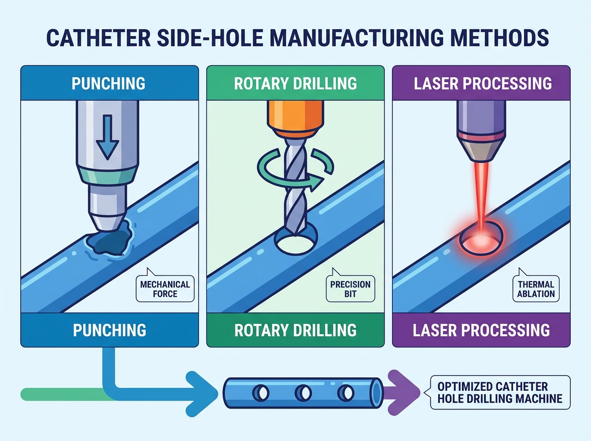
A rotary catheter drilling machine bridges the gap between raw speed and high precision. These systems utilize high-speed spindles, often exceeding 60,000 to 100,000 RPM, combined with multi-axis CNC control. The solid carbide drill bit cuts through the polymer while a precision mandrel supports the internal lumen. The CNC system dictates exact feed rates, ensuring the bit removes material cleanly without pushing, heating, or deforming the tube.
Produces exceptionally clean, burr-free edges across a wide range of thermoplastics and elastomers.
Highly effective for multi-lumen Central Venous Catheters (CVCs) where depth control prevents piercing inner septums.
Processes braided or coiled reinforced shafts without unraveling the internal stainless steel or nitinol wire architecture.
Multi-axis interpolation allows for the creation of angled skives and non-circular ports using standard end mills.
Rotary drilling cycle times are generally slower than mechanical punching. When a device requires an array of multiple holes, the spindle must index to each location, increasing total processing time. Swarf management presents another significant challenge. The cutting process generates polymer chips. Machines must feature robust, high-velocity vacuum extraction systems right at the cutting zone to prevent these chips from contaminating the internal lumen. Furthermore, operations teams must manage the inventory and replacement schedules for high-precision micro-drill bits. Operating with worn bits immediately degrades edge quality, increases cutting temperatures, and elevates the risk of part rejection.
Success in rotary drilling relies entirely on the chip load. If the feed rate is too slow relative to the spindle speed, the bit rubs against the polymer instead of cutting it. This friction generates heat, melting the plastic and causing it to wrap around the tool. If the feed rate is too fast, the bit pushes the material inward, creating a burr on the inner diameter. Engineers must dial in these parameters for every specific polymer blend. Peck drilling cycles—where the bit advances, retracts to clear chips, and advances again—are often necessary for thick-walled extrusions to maintain a clean hole profile.
Laser processing eliminates physical contact with the catheter entirely. This technology uses focused light to ablate material. Manufacturers typically deploy UV Excimer lasers for cold ablation or Femtosecond/Picosecond lasers for ultra-short pulse processing. Cold ablation breaks molecular bonds without transferring heat, while ultra-short pulses vaporize material faster than thermal energy can spread into the surrounding polymer matrix.
Zero mechanical contact eliminates material deformation, internal mandrels, and physical tooling wear.
Achieves micron-level accuracy for highly complex, programmable geometries like tapered holes, stars, and micro-pores.
Ideal for ultra-thin walls and sensitive neurovascular, ophthalmic, or cardiovascular microcatheters.
Easily transitions between different hole patterns via software updates rather than physical tooling changes.
Laser systems require significant facility upgrades. Installation demands Class 1 laser safety enclosures and specialized exhaust systems to handle toxic fumes generated during ablation. Thermal damage remains a persistent risk. If pulse parameters, frequency, and wavelengths are not perfectly tuned to the specific polymer, the laser will melt the material. This creates a Heat Affected Zone (HAZ), altering the polymer's mechanical properties and potentially embrittling the catheter wall. Finally, laser ablation is relatively slow for large-diameter drainage holes, as the beam must trace and vaporize a significant volume of material layer by layer.
The HAZ is the area immediately surrounding the laser cut where the polymer has absorbed excess thermal energy. In materials like polyurethane, a large HAZ leads to localized hardening. When the catheter flexes, this hardened ring acts as a stress riser, leading to premature mechanical failure. Engineers mitigate HAZ by utilizing gas assist during the cutting process. A stream of inert gas, such as argon or nitrogen, blows across the cutting zone. This gas cools the material, prevents oxidation, and rapidly evacuates the vaporized polymer plume before it can condense back onto the catheter surface.
Selecting a catheter hole drilling machine requires mapping machine capabilities directly to your device specifications. High-volume urology catheters demand different processing methods than low-volume, high-value neurovascular devices. Engineering teams must evaluate material compatibility, lumen architecture, and automation requirements to ensure the equipment aligns with the production floor strategy.
Commodity devices like PVC suction catheters or standard PTFE sheaths benefit from the raw speed of mechanical punching. The rigid nature of these materials allows them to shear cleanly. Structural heart devices, electrophysiology catheters, and multi-lumen CVCs require the precise depth control of rotary drilling. The ability to cut through a Pebax outer jacket and a nitinol braid simultaneously makes rotary systems indispensable for reinforced shafts. Delicate silicone microcatheters or ultra-thin polyurethane balloons necessitate laser processing to avoid crushing the fragile walls under mechanical load.
Processing Method | Optimal Materials | Sub-Optimal Materials | Best Use Case |
|---|---|---|---|
Mechanical Punching | Rigid PVC, PTFE, High-Durometer Pebax | Silicone, Low-Durometer Polyurethane | Single-lumen commodity drainage |
Rotary Drilling | Braided Shafts, Medium-Durometer Thermoplastics | Ultra-thin walled microcatheters | Multi-lumen CVCs, Angled Skives |
Laser Processing | Silicone, Polyimide, Thin-wall Polyurethane | Thick-walled, large diameter PVC | Neurovascular, complex micro-pores |
Production workflows dictate machine configuration. Reel-to-reel continuous processing suits mechanical punching perfectly. The tubing feeds directly from the extruder, gets punched, and spools onto a collection reel without human intervention. Rotary and laser systems often utilize discrete, cut-to-length part loading. Operators or robotic arms load pre-cut shafts onto mandrels or into collets. When evaluating equipment, consider how the material handling mechanism integrates with your existing cleanroom footprint and labor availability. Automated hopper feeds can bridge the gap for discrete parts, allowing one operator to manage multiple rotary or laser stations simultaneously.
Deploying new manufacturing equipment introduces process variables. Engineering teams must anticipate validation hurdles, inspection requirements, and facility constraints before installation. Failing to plan for these operational realities results in idle machinery and delayed product launches.
Validation proves the process consistently produces devices meeting predetermined specifications. Mechanical punching requires proving that die wear does not cause unacceptable flash over a defined lot size. You must establish a hard limit on the number of strokes before mandatory tool replacement. Rotary drilling validation focuses on spindle runout, feed rates, and particulate counts. Laser validation requires proving beam stability, focal depth consistency, and thermal limits. You must demonstrate through tensile testing that the HAZ does not compromise the shaft's mechanical integrity.
Automated vision inspection systems are mandatory for high-yield production. Regardless of the drilling method, high-resolution cameras must verify hole placement, diameter, and the absence of flash in real-time. Advanced systems use closed-loop feedback. If a rotary drill bit begins to wear and hole diameters shrink, the vision system detects the trend and alerts the operator before the parts fall out of tolerance. Integrating vision systems directly into the drilling machine reduces separate inspection bottlenecks and prevents bad parts from moving downstream.
Cleanroom floor space is expensive. Mechanical punches boast small footprints and require standard compressed air and power. Rotary drilling machines require slightly more space for CNC controllers and vacuum swarf extraction units. Laser systems demand the most infrastructure. You must provide specialized power drops, heavy-duty fume extraction, and dedicated chillers to maintain laser optic temperatures. Map these utility requirements during the procurement phase to avoid costly installation delays. Ensure your HVAC system can handle the makeup air required by the laser's fume extraction unit.
Request proof-of-concept sample processing from equipment vendors using your exact polymer blends and tubing dimensions.
Require detailed cycle-time estimates based on your specific hole array patterns to calculate realistic daily throughput.
Audit the vendor's tooling lead times and consumable availability to ensure continuous production uptime.
Map the required facility utilities, including vacuum extraction and power drops, against your current cleanroom capabilities.
A: Tolerances typically range from ±0.001” to ±0.005”. The exact tolerance depends on the application, material durometer, and manufacturing method. Laser processing achieves the tightest tolerances, while mechanical punching operates at the higher end of that range.
A: These machines use precision depth-control sensors and multi-axis CNC programming. The spindle advances the drill bit to an exact depth, cutting through the outer wall without puncturing the internal septums separating the lumens. Specialized mandrels also support the internal geometry.
A: Yes, but it presents challenges due to differing ablation thresholds between polymers and metals. Ultra-short pulse lasers address this by vaporizing the material instantly, cutting through both polymer and metal wire before thermal energy can transfer and melt the surrounding plastic.
A: Mechanical punching is near-instantaneous, often processing multiple holes per second in a continuous feed. Laser drilling cycle times depend on hole size, material thickness, and ablation rate. Lasers can take several seconds per hole for larger diameters.
A: For mechanical methods, maintain sharp tooling and optimize die clearance. In rotary drilling, use exact spindle speeds and feed rates matched to the material, paired with strong vacuum extraction. For laser processing, optimize pulse parameters and use gas assist.
A: Advanced rotary and laser systems with multi-axis capabilities can perform both operations on the same machine. Traditional mechanical punching is usually limited to fixed geometries dictated by the physical die, requiring separate setups for perpendicular holes and angled skives.
A: Mechanical punches require daily die inspections and frequent sharpening. Rotary systems need regular drill bit replacement, spindle runout checks, and vacuum filter cleaning. Laser systems demand routine optics cleaning, chiller fluid top-offs, and periodic beam alignment verification.
